C22 Keel Restoration - Part 2

Post All Keel Topics Here
Post Reply
User avatar
C22Bob
Site Admin
Site Admin
Posts: 143
Joined: Mon Sep 24, 2012 12:03 pm
Location: Knoxville TN

C22 Keel Restoration - Part 2

Post by C22Bob »

The Bracket
IMG-20150414-00149.jpg
IMG-20150414-00151.jpg
All Stainless Steel 304 parts sourced from McMaster-Carr
3/8" Plate
Pipe with 3/4" bore for main sleeve
Half-Coupling 3/4" NPT to hold the plug
Hardened 3/4" shaft
Brass 3/4" NPT plug

The welding is a bit crude, but will do the job. I'm not trying to win any welding awards :)


I changed my design slightly from some others I've seen here. I brought more (3/8") of the main sleeve out to the keel. The more sleeve steel there the better. The gap has to closed with something and using washers gives zero support. With this, I only have to close an 1/8" gap each side which I'll do with SS washers. Caveat - The keel can't be raised into the trunk in the full horizontal position since the keel sleeve area is 2" thick and the keel top is 2.5". Instead, raise the keel in the 60 degree position and then engage the shaft.
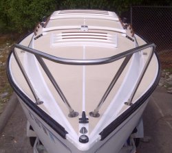

The Trunk

Here's the original. I don't understand why the half-moon cutout in the trunk wall.
IMG-20140416-00229.jpg
At any rate, I fashioned my own 1/4" aluminum plates to fill those sections.
IMG-20150418-00157.jpg
Plates installed and sandwiched tight with Marine-TEx structural epoxy
IMG-20150421-00172.jpg
The Keel

My 1980 C22 had the snubber, top and aft which is a plumbing flange with plastic rod inside. I like the idea of a stablilzer for the keel so I took that a step further. Installed SS skid plates each side at top. I'll mount new SS flanges with plugs in aft keel trunk to pinch the keel from the 0 - 60 degree position
IMG-20150418-00161.jpg
Basic concept
IMG-20150418-00163.jpg
More to come... :)
Reality
Posts: 185
Joined: Sat Oct 11, 2014 7:11 pm
Location: Ellison Bay, WI

Post by Reality »

great photos and great work. re the half moon shape, I'd speculate from my experience doing design engineering in the decade these boats were made that it's the common practice of using large radius edges wherever possible to minimize stress cracking of either the plate or the cutout. A square plate and square cutout is much more likely to experience a stress fracture with something as heavy as the rudder and the forces exerted by the water while sailing. Again, great work.
User avatar
astrorad
Posts: 730
Joined: Fri Feb 19, 2010 8:09 pm
Location: s.e Wisconsin

Post by astrorad »

Nice work Bob and good ideas. My keel was very tight with very little clearance between it and the keel brackets. It was a snug fit jacking it back up into position to install my new pin. I cleaned up the old pipe fitting snubber, painted it with rustoleum black and greased the inside. I then shortened up the nylon rod and put a heavy spring between the rod and the pipe cap to provide tension. I know it isn't the best system, but it worked pretty well for over thirty some years that the boat was sailed.
Bill
Post Reply